
| Relevant standards |
-
IEC 958 (International Electrotechnical commission)
-
AES 3-199x (Audio Engineering Society) - TC 84 (Audio Engineering Society)
-
ANSI S4.40-1985
-
EIAJ CP-340
-
IEC958
-
Data Book Crystal, AN21REV1: "AES/EBU Interface" from C. Sanchez &
R. Taylor
| Index: |
| General rules: |
| The
digital audio interface AES/EBU have been designed to interconnect various
equipments in digital format. A variant of this interface is used in consumer
products (SPD/IF). In that case, the physical layer can be optical or coaxial
(Cinch). In the professional format, interface can be coaxial (BNC or CINCH)
or twisted shielded pair (CANON). Normally, professional equipments can
accept consumer format, sometimes removing copy management bit at the same
time. (SCMS).
The digital audio interface AES/EBU is a way to transmit sequentially audio data through a simple transmission line. Up to two audio channels can be transmitted simultaneously and there is a method to add control informations and error correction protocol. The control informations are transmitted 1 bit per audio sample, and must be accumulated in a buffer to make a bloc structure. Data encoding is a biphase modulations, authoring received to extract clock from data. Coding violations, called preambles are used to identify the beginning of a sample or a block. |
| Frames, sub-frames & Blocks: |
| An
audio data is placed in a structure, called sub-frame.
The sub-frame as described in figure 1, consist of 4 bits preamble, 4 auxiliary data bits , 20 bits of audio data, 3 bits named validity, user and channel status , and one parity bit. |

| Preamble
is containing biphase mark violations allowing to identify start of a sub-frame.
Audio sample length can be up to 24 bits and is transmitted least significant bit first. If audio sample length is more than 20 bits, auxiliary data bits are used to transmit bits >20. if audio sample length i < 20 bits, the auxiliary data bits can be used for others applications, like vocal transmissions Parity bit is set for even parity. The Validity bit (low level active), indicating that the audio sample is ready for conversion. User bits and channel status are sent one bit per sample and must be proceeded after accumulation during a complete bloc transmission. Users bits usage is undefined, and can be used for any purpose. Channel status bits are giving important informations about audio data and transmission line. Each audio channel have got is own structure, and every 192 samples, a channel status bloc can be recovered. As indicated in figure 2, two consecutive samples are forming a frame (containing A and B samples), ad 192 frames are forming a block. Preamble identifying sub-frame start is different for each channel (X and Y), a third one (Z) allowing to detect start of block. |

| Biphase mark modulation: |
| Data are transmitted using biphase mark encoding, to reduce DC offset, allowing to extract clock from Data (this is used also in SMPTE time code). As indicated in figure 3, after biphase encoding, there is two changes of signal for each 1 transmitted, instead of 1 change for 0. Polarity is changing for each bit limit. So it is not possible to get polarity in the middle of the bit transmission to identify bit sign (unlike RS232). | 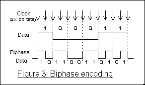 |
| Preambles: |
| Each
sub-frame starts with a preamble. This allow received to lock receiver
from the first sub-frame.
There is 3 defined preambles: |
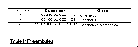
| In table 1, preambles are shown with to bit patterns, because signal polarity in biphase mark is not conserved. To distinguish a preamble from a data, each one content 2 biphase marks violation. Biphase encoding ask for polarity change each clock, but in the preamble, violations of that convention is done 2 times. In figure 3, each bit limit (indicated by a dotted line) contain a state change. In figure 4, there is two bit limits without transitions, to allow preamble detection. Preamble X and Y are indicating respectively Channels A and B, preamble Z is replacing preamble X each 192 frame to mark start of a status block. | 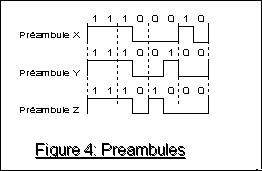 |
| There is two Channel status blocks, once for channel A the other for channel B. Because is block is made of 192 frames, the channel status block is 192 bits long. Those bits must be arranged to be seen like a 24 bytes block. Blocks can have two different formats: the professional format (AES/EBU) and the consumer format (SPDIF). The first bit of the block is indicating the format (0=CONSUMER et 1=PROFESSIONAL). |
| Professional Status Block Format (AES/EBU): |
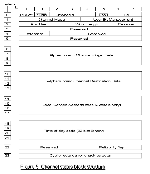
| Positioning
to 1 the first bit of channel status bloc (PRO), we are selecting the professional
format (broadcast). Status block structure for professional format is detailed
in Figure 5.
Table 2 explain each bit signification. Zones described as reserved, are not defined for the moment, and must be set to 0 while transmitting. Most of those informations have been extracted from AES 3-1985, others from AES 3-199x. AES specifications moving a lot , informations in this document are not guaranteed. |
| Consumer Status Block Format (SPD/IF): |
| Positioning
to 0 the the first bit of the channel status block is switching to consumer
format or SPD/IF. Consumer status block structure is detailed in Figure
6.
Table 3 is showing bits and bytes and their signification. Zones described as reserved, are not defined for the moment, and must be set to 0 while transmitting. Most of those informations have been extracted from AES-1985, others from AES-199x. AES specifications moving a lot , informations in this document are not guaranteed. |
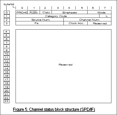
| In
the consumer format, bit 0 must be set to 0. If bit one is set to one,
setting data as non-audio, the bits 3 to 5 are changing of signification
(see table 3 byte 0). Bits 6 & 7 are defining mode. 1 mode is defined
today (mode=00=). This mode is redefining the following 3 bytes as described
in figure 6.
Most of bits of byte 1 are defining the category code. The first 3 bits (from 5 defined) are defining general category. From the laser category, there is compact disc ( code=1000000). This format is defining some of the channel U bits and sub code from cd port. Complementary information can be obtained from CP340 IEC-958 documents. |
| Serial Copy Managemen System (SCMS): |
| Actually,
standards committees are working on a minimal implementation of channel
status bits.
An algorithm for copy protection is also implemented. This is called SCMS or Serial Copy Management System. It's using category code ,COPY and L bits to find if copy is possible.
Example: If the category code shows it's a CD (1000000) , and the couple of copy bits is oscillating to a 10 Hz frequency, That's because the cd is a copy of the an original and the copy is not any more allowed. |